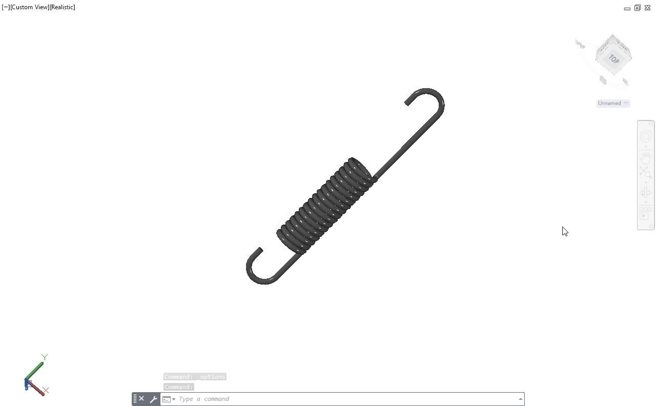
3D Helical Spring Modelling
This project is a 3D model of a helical spring created in AutoCAD. I made this to practice 3D modeling tools and to understand how a spring is represented in mechanical design.
Mechanical CAD Designer
📍 Based in Mumbai, India
Entry-level Mechanical CAD Designer with hands-on experience in SolidWorks and AutoCAD, specializing in part modeling, assemblies, sheet metal, weldments, and manufacturing drawings. Skilled in creating accurate 2D drawings from 3D models, interpreting engineering drawings, and supporting design modifications. Actively seeking junior, trainee, contract, or remote CAD design opportunities.
This project is a 3D model of a helical spring created in AutoCAD. I made this to practice 3D modeling tools and to understand how a spring is represented in mechanical design.
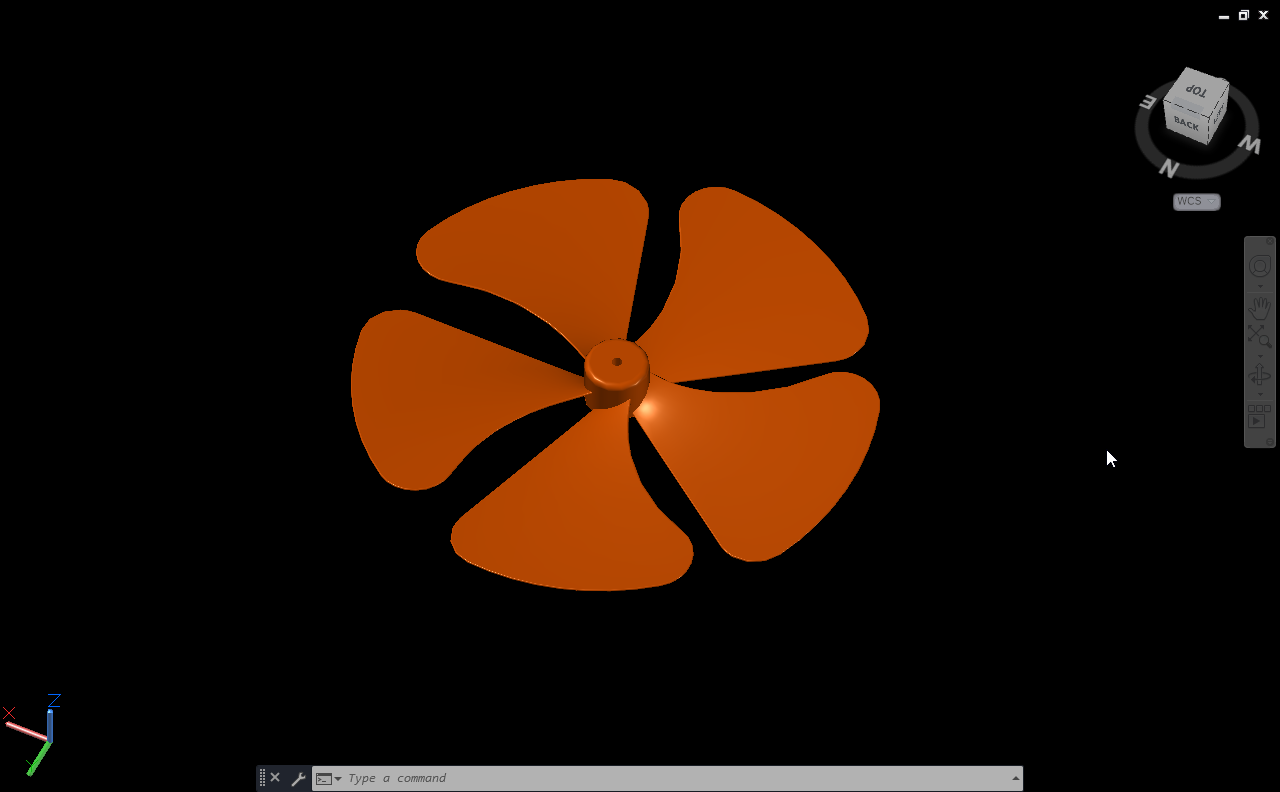
This project focuses on creating a detailed 3D fan blade using AutoCAD. It helped me practice surface modeling techniques and study how curvature and rotation affect the final design.
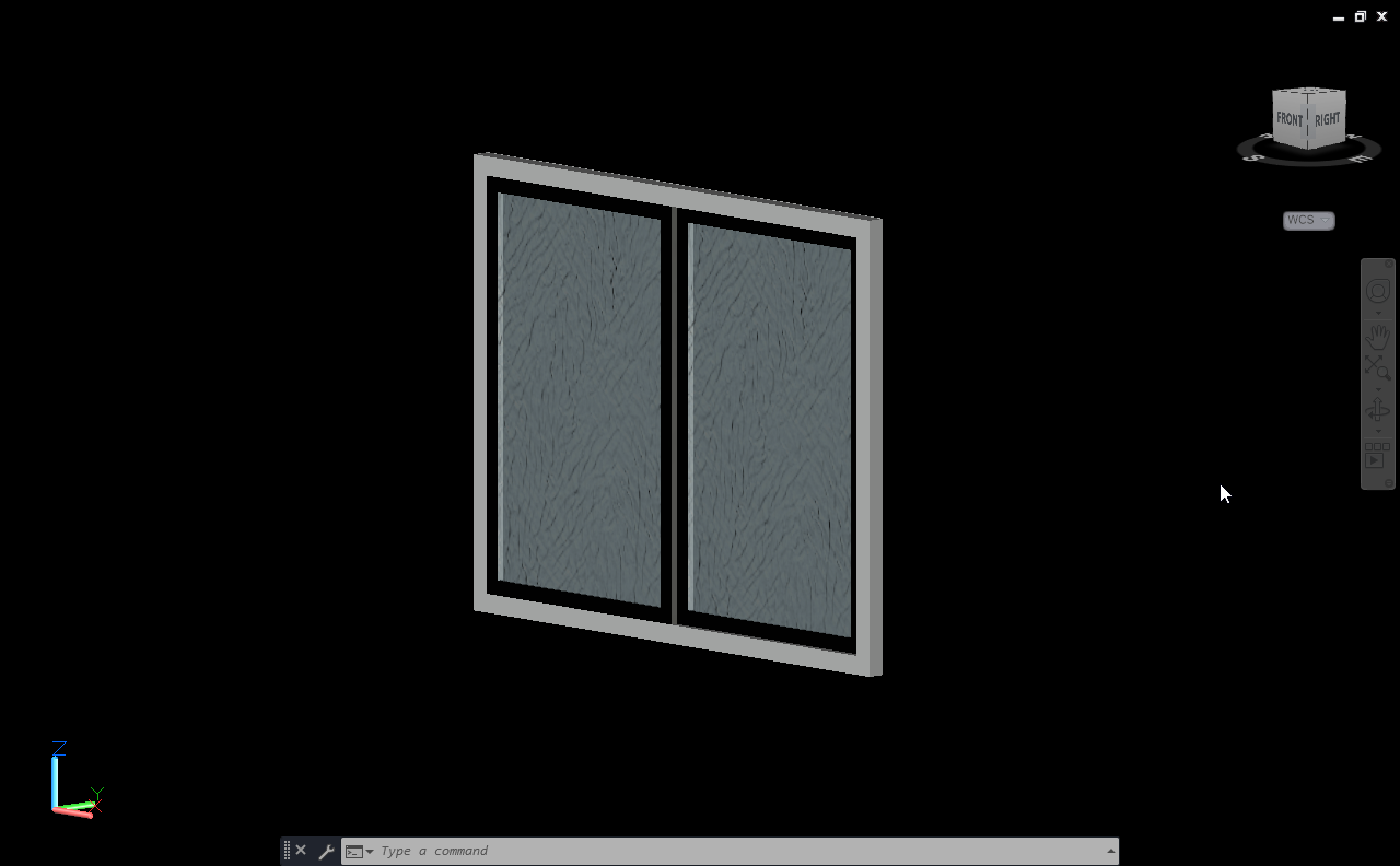
I made this project for a local fabrication shop to understand how mechanical drawings are converted into real-world structures.
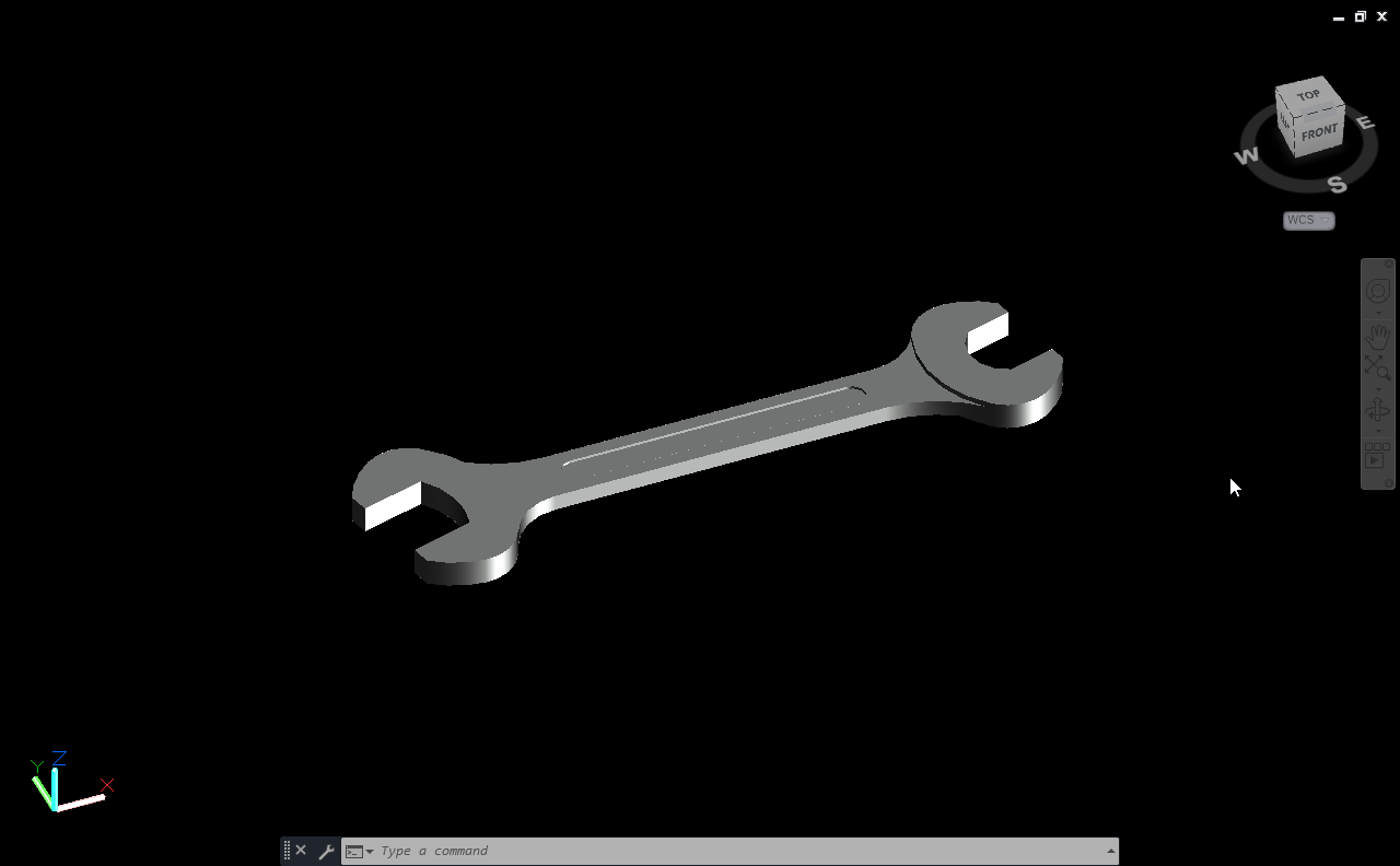
I made this project just out of curiosity. I saw a spanner at home and decided to model it in AutoCAD by taking real measurements using a Vernier caliper.
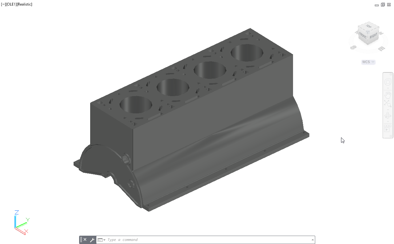
The aim of this project was to understand how each part is shaped, sized, and connected inside the engine assembly.
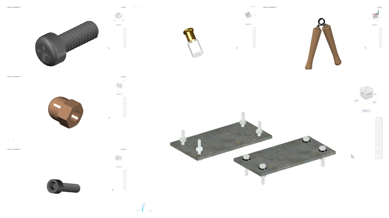
This project is a collection of small 3D models that I created for practice and experimentation.
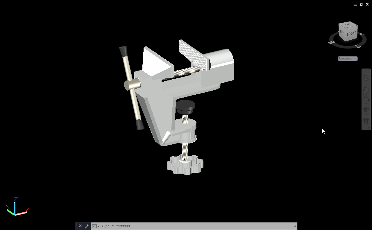
I created each component separately including the base, fixed jaw, movable jaw, screw, and handle, and then combined them to form the full assembly.
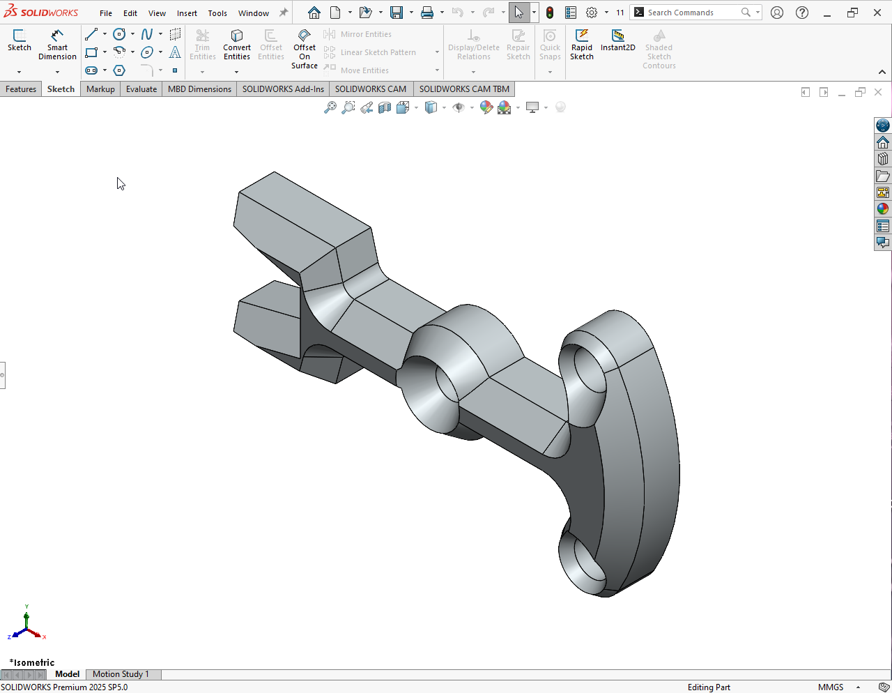
Created a 3D link bracket model in SolidWorks to demonstrate mechanical design principles, part modeling techniques, and proper use of features and constraints.
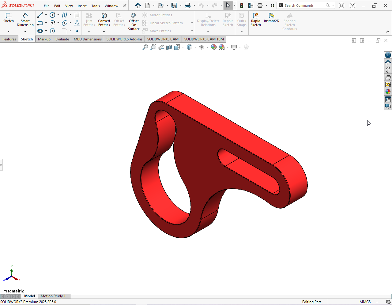
This project is a 3D model of a hook bracket created in SolidWorks, focusing on basic mechanical design and accurate part modeling.
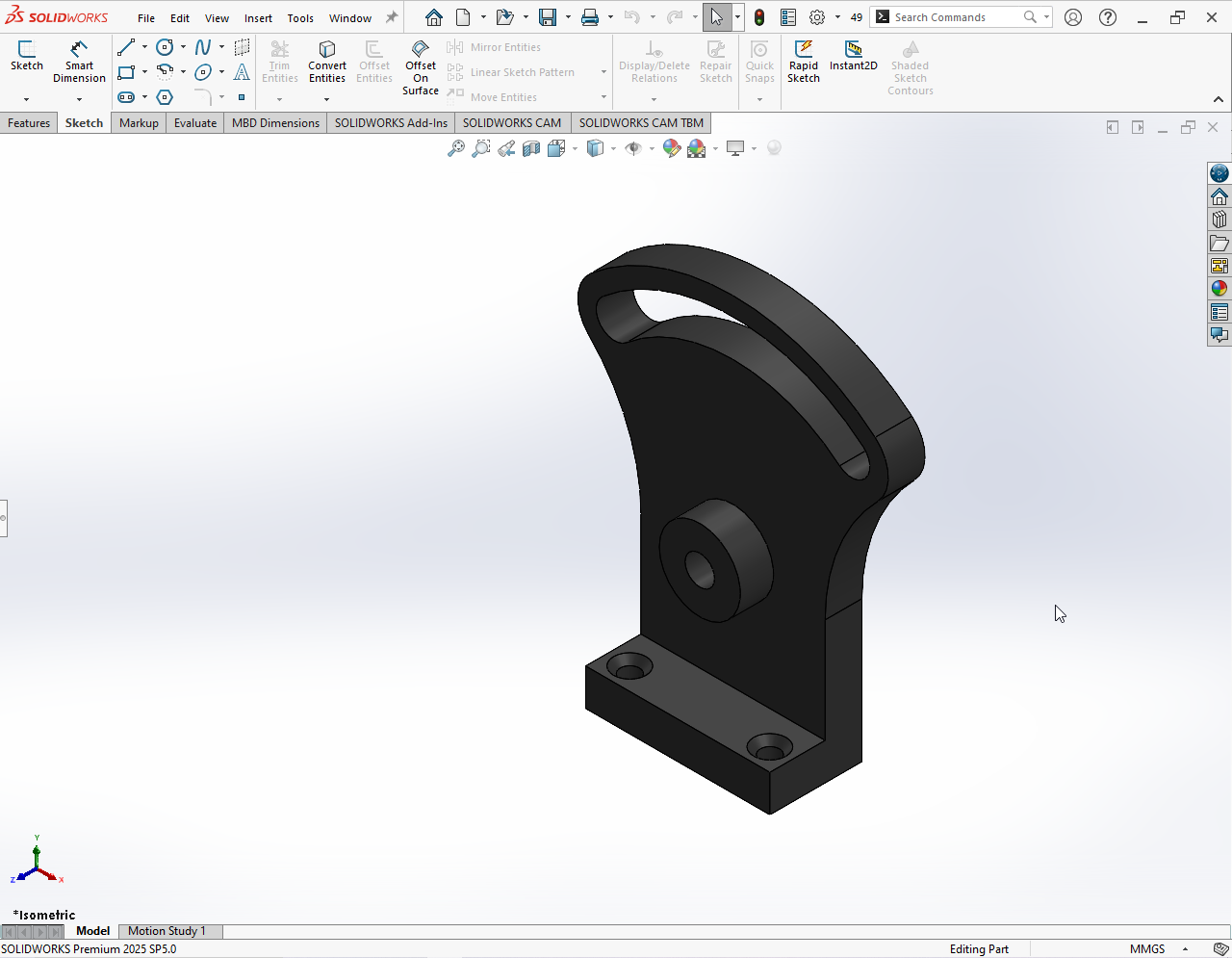
Designed and modeled a 3D mounting bracket using SolidWorks. The project focuses on accurate part modeling, proper dimensions, and clean geometry suitable for mechanical mounting applications.
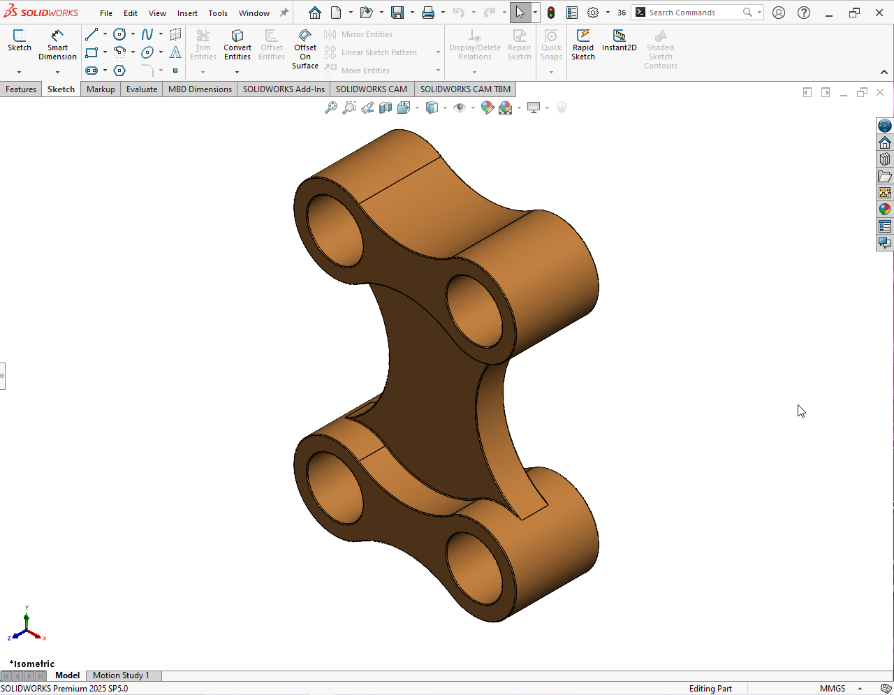
Designed and modeled a Double Lug Link using SolidWorks. Created accurate 3D geometry with proper dimensions and constraints. Prepared clean technical drawings suitable for manufacturing and assembly reference.
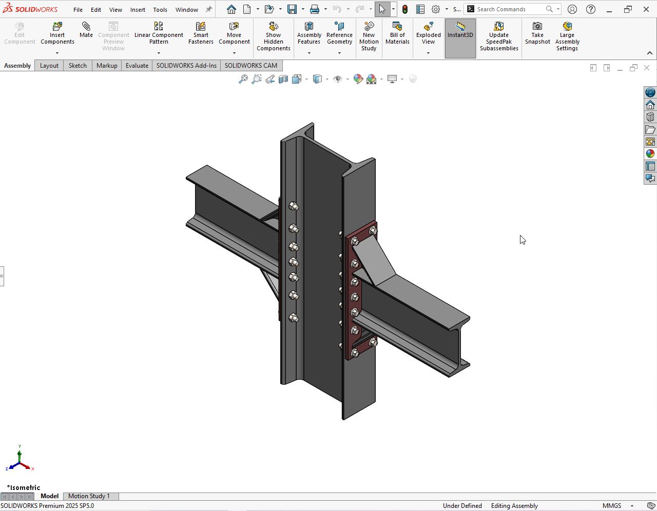
Designed weldment structures in SolidWorks using structural members and trim/extend features, and prepared fabrication drawings.
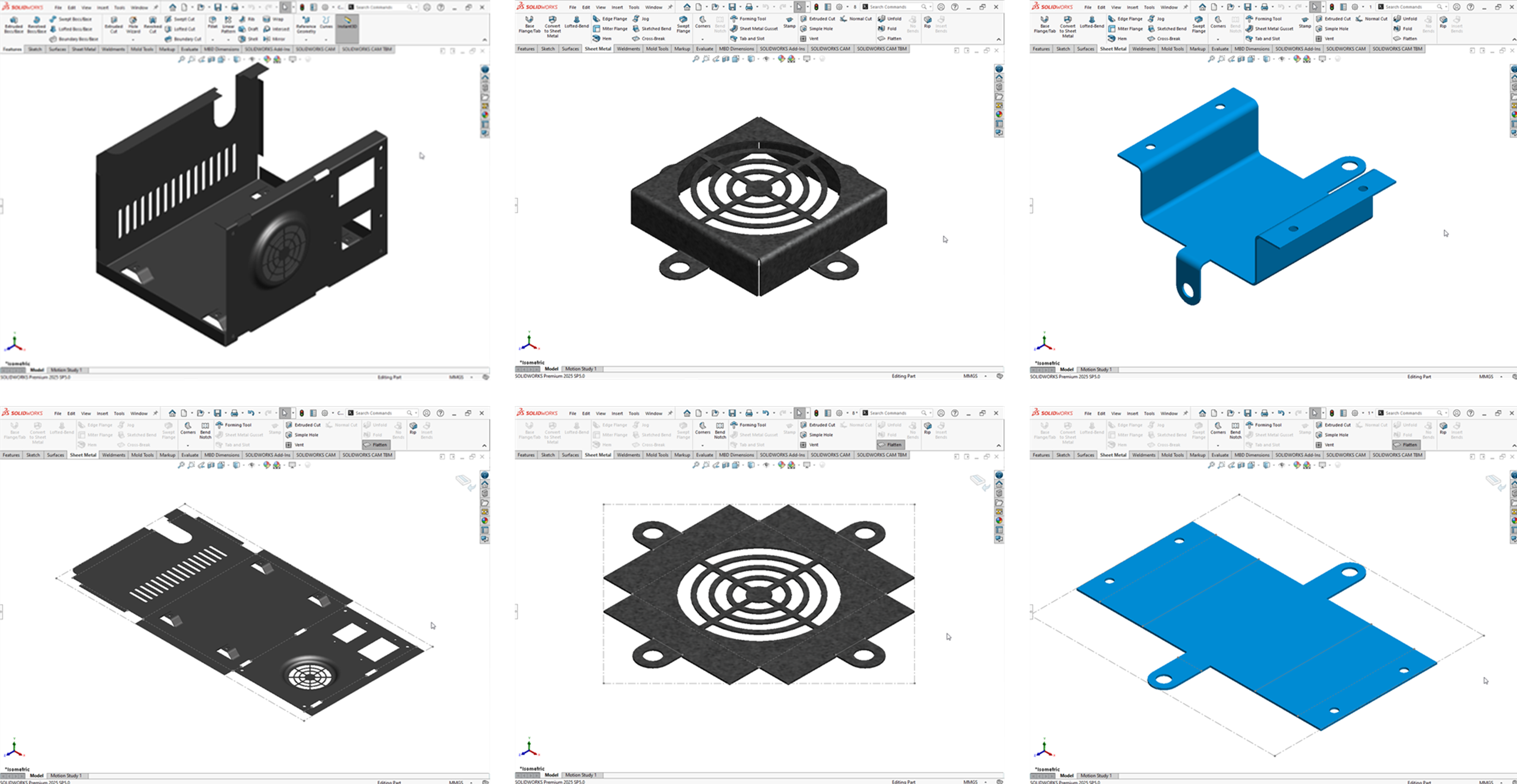
Designed a sheet metal component in SolidWorks with flanges, bends, and cuts, and created flat patterns and detailed drawings for manufacturing.
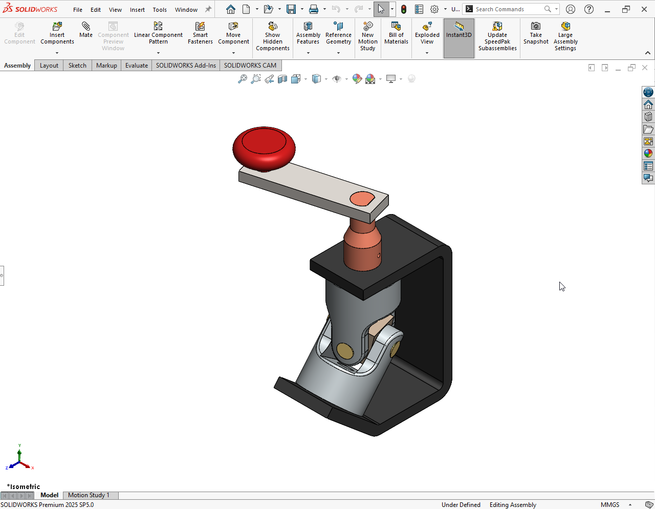
I modeled each component of the Universal Coupling Joint individually and assembled them using proper mates, then conducted a motion study to analyze rotational movement and power transmission.